

Led Blinking using Transistor
This is simple blinking led project anyone with basic
knowledge of simple circuit connecting can easily perform this one. The circuit is built using transistors, resistors, capacitors,
and LEDs.
Required Components:
- PNP Transistor, P/N 2907A, qty: 2
- Resistor, value 470 Ohms, qty: 2
- Resistor, value 100k Ohms, qty: 2
- Capacitor, 10 uF, qty: 2
- LED, Qty: 2
- Breadboard
- Jumper wires
We will complete the project in following five steps:
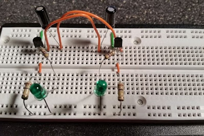
Step 1: Add the transistors

Add the two PNP transistors and the jumper wires
from the power BUS to the emitter of each transistor. Because of the way I
inserted the two transistors the emitter is on the left side of both
transistors.
Step 2: Add capacitors

Connect the two capacitors to the circuit. Connect the positive
lead of the first capacitor to the collector of transistor 2. Next connect the
negative lead of the same capacitor to the base of transistor 1.
Repeat the above process for the
second capacitor. Connect the positive lead of the second capacitor to the
collector of transistor 1. Connect the negative lead of the same capacitor to
the base of transistor 2.
Step 3: Add 100k resistor

Next connect the 100k resistors to the
transistors. One lead of the resistor connects to the Base of the transistor,
the other lead connects to ground. Do this for both transistors.
Step 4: Add LEDs

Finally add the two 470 Ohm resistors along with the two LEDs. I
added a picture of a transistor to identify the Emitter, Base, and Collector.
Connect one wire of the first
resistor to the collector of transistor 1. The the other resistor wire then
connects to the positive wire of the first LED. The negative wire of the LED is
then connected to ground.
Follow the same steps for the
other resistor and LED. Connect one wire of the second resistor to the
collector of transistor 2. The the other resistor wire then connects to the
positive wire of the second LED. The negative wire of the LED is then connected
to ground.
Step 5: Power supply

The last step is to supply power and watch the LEDs blink. I use a
9 volt battery and it worked fine.
For fun you can try other
capacitor values to change the rate at which the LEDs blink.


Great
ReplyDelete