

Introduction to Star-Delta Starter
Most
induction motors are started directly on line, but when very large motors are
started that way, they cause a disturbance of voltage on the supply lines due
to large starting current surges. To limit the starting current surge, large induction motors are started
at reduced voltage and then have full supply voltage reconnected when they run
up to near rotated speed
A star delta
starter is the most commonly used method for the starting of a 3-phase
induction motor. In star delta starting an induction motor is connected in
through a star connection throughout the starting period. Then once the motor
reaches the required speed the motor is connected through delta connection.
Star Delta Consists Of
- Contactors (Main, star and delta contactors) 3 No’s (For Open State Starter) or 4 No’s (Close Transient Starter).
- Time relay (pull-in delayed) 1 No.
- Three-pole thermal overcurrent release 1 No.
- Fuse elements or automatic cut-outs for the main circuit 3 Nos.
- Fuse element or automatic cut-out for the control circuit 1No.
Working Mechanism
This is the
reduced voltage starting method. Voltage reduction during star-delta starting
is achieved by physically reconfiguring the motor windings as illustrated in
the figure below. During starting the motor windings are connected in star
configuration and this reduces the voltage across each winding 3. This also
reduces the torque by a factor of three.

After a
period of time the winding are reconfigured as delta and the motor runs
normally. Star/Delta starters are probably the most common reduced voltage
starters. They are used in an attempt to reduce the start current applied to
the motor during start as a means of reducing the disturbances and interference
on the electrical supply.
The
Star/Delta starter is manufactured from three contactors, a timer and a thermal
overload. The contactors are smaller than the single contactor used in a Direct
on Line starter as they are controlling winding currents only. The currents
through the winding are 1/root 3 (58%) of the current in the line.
There are
two contactors that are close during run, often referred to as the main
contractor and the delta contactor. These are AC3 rated at 58% of the current
rating of the motor. The third contactor is the star contactor and that only
carries star current while the motor is connected in star.
The current
in star is one third of the current in delta, so this contactor can be AC3
rated at one third (33%) of the motor rating.
Power Circuit

The main
circuit breaker serves as the main power supply switch that supplies
electricity to the power circuit.
The main
contactor connects the reference source voltage R, Y, B to
the primary terminal of the motor U1, V1, W1.
In
operation, the Main Contactor (KM3) and the Star Contactor (KM1) are closed
initially, and then after a period of time, the star contactor is opened, and
then the delta contactor (KM2) is closed. The control of the contactors is by
the timer (K1T) built into the starter. The Star and Delta are electrically
interlocked and preferably mechanically interlocked as well.

Star State: The Main [KM3] and the Star [KM1] contactors are closed and the delta [KM2] contactor is open. The motor is connected in star and will produce one third of DOL torque at one third of DOL current.
Open State: This type of operation is called open transition switching because there is an open state between the star state and the delta state. The Main contractor is closed and the Delta and Star contactors are open. There is voltage on one end of the motor windings, but the other end is open so no current can flow. The motor has a spinning rotor and behaves like a generator.
Delta State: The Main and the Delta contactors are closed. The Star contactor is open. The motor is connected to full line voltage and full power and torque are available
The star
contactor serves to initially short the secondary terminal of the motor U2, V2,
W2 for the start sequence during the initial run of the motor from standstill.
This provides one third of DOL current to the motor, thus reducing the high
inrush current inherent with large capacity motors at startup.
Controlling
the interchanging star connection and delta connection of an AC induction motor is
achieved by means of a star delta or wye delta control circuit. The control
circuit consists of push button switches, auxiliary contacts and a timer.
Control Circuit For Star Delta Starter
The ON push
button starts the circuit by initially energizing Star Contactor Coil (KM1) of
star circuit and Timer Coil (KT) circuit. When Star Contactor Coil (KM1)
energized, Star Main and Auxiliary contactor change its position from NO to NC.
When Star
Auxiliary Contactor (1) (which is placed on Main Contactor coil circuit )
become NO to NC it’s complete The Circuit of Main contactor Coil (KM3) so Main
Contactor Coil energized and Main Contactor’s Main and Auxiliary
Contactor Change its Position from NO to NC. This sequence happens in a
friction of time.
After pushing
the ON push button switch, the auxiliary contact of the main
contactor coil (2) which is connected in parallel across the ON push button
will become NO to NC, thereby providing a latch to hold the main contactor coil
activated which eventually maintains the control circuit active even after
releasing the ON push button switch.
When Star
Main Contactor (KM1) close its connect Motor connects on STAR and it’s
connected in STAR until Time Delay Auxiliary contact KT (3) become NC to NO.
Once the
time delay is reached its specified Time, the timer’s auxiliary contacts
(KT)(3) in Star Coil circuit will change its position from NC to NO and at the
Same Time Auxiliary contactor (KT) in Delta Coil Circuit(4) change its
Position from NO To NC so Delta coil energized and Delta Main Contactor
becomes NO To NC. Now Motor terminal connection change from star to delta
connection.
A normally
close auxiliary contact from both star and delta contactors (5&6)are also
placed opposite of both star and delta contactor coils, these interlock
contacts serves as safety switches to prevent simultaneous activation of both
star and delta contactor coils, so that one cannot be activated without the
other deactivated first. Thus, the delta contactor coil cannot be active when
the star contactor coil is active, and similarly, the star contactor coil
cannot also be active while the delta contactor coil is active.
The control
circuit above also provides two interrupting contacts to shutdown the motor.
The OFF push button switch break the control circuit and the
motor when necessary. The thermal overload contact is a protective device which
automatically opens the STOP Control circuit in case when motor
overload current is detected by the thermal overload relay, this is to prevent
burning of the motor in case of excessive load beyond the rated capacity of the
motor is detected by the thermal overload relay.
At some
point during starting it is necessary to change from a star connected winding
to a delta connected winding. Power and control circuits can be arranged to
this in one of two ways – open transition or closed transition.
Open Transition Starter
Discuss
mention above is called open transition switching because there is an open
state between the star state and the delta state.
In open
transition the power is disconnected from the motor while the winding are
reconfigured via external switching.
When a motor
is driven by the supply, either at full speed or at part speed, there is a
rotating magnetic field in the stator. This field is rotating at line frequency.
The flux from the stator field induces a current in the rotor and this in turn
results in a rotor magnetic field.
When the
motor is disconnected from the supply (open transition) there is a spinning
rotor within the stator and the rotor has a magnetic field. Due to the low
impedance of the rotor circuit, the time constant is quite long and the action
of the spinning rotor field within the stator is that of a generator which
generates voltage at a frequency determined by the speed of the rotor.
Note:
When the motor
is reconnected to the supply, it is reclosing onto an unsynchronized generator
and this result in a very high current and torque transient. The
magnitude of the transient is dependent on the phase relationship between the
generated voltage and the line voltage at the point of closure can be much
higher than DOL current and torque and can result in electrical and mechanical
damage.
Open
transition starting is the easiest to implement in terms or cost and circuitry
and if the timing of the changeover is good, this method can work well. In
practice though it is difficult to set the necessary timing to operate
correctly and disconnection/reconnection of the supply can cause significant
voltage/current transients.
Four states of open transition
OFF State: All Contactors are open.
Star State: The Main [KM3] and the Star [KM1] contactors are closed and the delta [KM2] contactor is open. The motor is connected in star and will produce one third of DOL torque at one third of DOL current.
Open State: This type of operation is called open transition switching because there is an open state between the star state and the delta state. The Main contractor is closed and the Delta and Star contactors are open. There is voltage on one end of the motor windings, but the other end is open so no current can flow. The motor has a spinning rotor and behaves like a generator.
Delta State: The Main and the Delta contactors are closed. The Star contactor is open. The motor is connected to full line voltage and full power and torque are available
Closed Transition Star-Delta Starter
There is a
technique to reduce the magnitude of the switching transients. This requires
the use of a fourth contactor and a set of three resistors. The resistors must
be sized such that considerable current is able to flow in the motor windings
while they are in circuit.
The
auxiliary contactor and resistors are connected across the delta contactor. In
operation, just before the star contactor opens, the auxiliary contactor closes
resulting in current flow via the resistors into the star connection. Once the
star contactor opens, current is able to flow round through the motor windings
to the supply via the resistors. These resistors are then shorted by the delta
contactor.
If the
resistance of the resistors is too high, they will not swamp the voltage
generated by the motor and will serve no purpose.
This is
achieved by introducing resistors to take up the current flow during the
winding changeover. A fourth contractor is required to place the resistor in circuit
before opening the star contactor and then removing the resistors once the
delta contactor is closed.
These
resistors need to be sized to carry the motor current. In addition to requiring
more switching devices, the control circuit is more complicated due to the need
to carry out resistor switching.
Five states of closed transition
OFF
State. All
Contactors are open
Star
State. The Main
[KM3] and the Star [KM1] contactors are closed and the delta [KM2] contactor is
open. The motor is connected in star and will produce one third of DOL torque
at one third of DOL current.
Star
Transition State. The
motor is connected in star and the resistors are connected across the delta
contactor via the aux [KM4] contactor.
Closed
Transition State. The
Main [KM3] contactor is closed and the Delta [KM2] and Star [KM1] contactors
are open. Current flows through the motor windings and the transition resistors
via KM4.
Delta
State. The Main
and the Delta contactors are closed. The transition resistors are shorted out.
The Star contactor is open. The motor is connected to full line voltage and
full power and torque are available.
Reason Behind Using Star Delta
We use star
delta which, is also called wye delta in north America, to reduce the inrush current
when the motor starts. When large induction motors start in delta their
starting current can be over 5 times higher than the full load current which
occurs when the motor stabilises and runs normally.
This huge
surge in current can cause lots of problems. The buildings electrical system
will be hit by this sudden large demand. The electrical infrastructure will
rapidly increase in temperature leading to component failure and even
electrical fires. The sudden demand also causes voltage drops throughout the
buildings electrical system which we can visually see because the lights will
dip, this can cause many problems for things such as computers and servers.
So to reduce
the starting current we simply need to reduce the starting voltage.
The star
configuration will reduce the coil voltage to around 58% compared to the delta
configuration. A lower voltage will lead to a lower current. The current in the
coil while in star configuration will be around ~33% of the delta
configuration. This will also lead to a reduction in torque, the star
configuration torque will also be around 33% compared to delta.
Inside Operation With Basic Example
Let consider
we have the motor connected in delta with supply voltage of 400V.
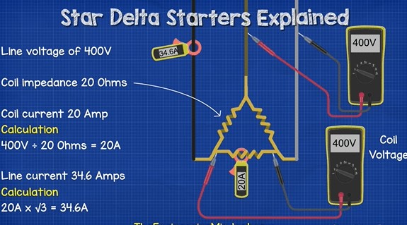
If we measure across the two ends of a coil, we again measure the line to line voltage of 400V. Let say each coil has a resistance, or impedance as this is AC power, of 20 Ohms. That means we will get a current reading on the coil of 20 Amp. We can calculate that from 400V / 20 Ohms = 20A. But the current in the line will be different, it will be 34.6A and we get that from 20A x sqr3 = 34.6A
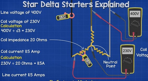
If we then
looked at a star connection. We again have a line to line voltage of 400V, if
we measure between any two phases. But, with the star connection all our coils
meet at the star point or neutral point. We can run a neutral line from this
point. So When we measure the voltage across the ends of the coil, we get a
lower value of 230V, that’s because the coil isn’t directly connected between
two phases like the delta version. One end is connected to a phase, the other
end is connected to a shared point, so the voltage is therefore shared and will
be less because one of the phases is always is reverse.
We can see
the 230V reading by dividing the 400V by sqr3 = 230V. As the voltage is less
the current will be too. If the coil is again 20ohms of resistance, or
impedance, then the current is calculated by 230V / 20ohms which is 11.5Amp.
The current in the line will also be 11.5A.
So with the
delta connection the coil is exposed to the full 400V between two phases. But
the star connection is only exposed to 230V between the phase and neutral. So
we can see that the star uses less voltage and therefore less current compared
to the delta version, which is why we use it first.
Features
- For low- to high-power three-phase motors.
- Reduced starting current
- Six connection cables
- Reduced starting torque
- Current peak on changeover from star to delta
- Mechanical load on changeover from star to delta
Advantages
- The operation of the star-delta method is simple and rugged
- It is relatively cheap compared to other reduced voltage methods.
- Good Torque/Current Performance.
- It draws 2 times starting current of the full load ampere of the motor connected


No comments:
Post a Comment