

What is PIR sensor?

PIR sensors is
a type of sensor to sense motion, almost always used to detect whether a human
has moved in or out of the sensors range.
They are small, inexpensive,
low power, easy to use and don't wear out. For that reason they are commonly
found in appliances and gadgets used in homes or businesses. They are often
referred to as PIR, "Passive Infrared", "Pyroelectric", or
"IR motion" sensors.
PIRs are
basically made of a Pyroelectric sensor which can detect levels of
infrared radiation. Everything emits some low level radiation, and the hotter
something is, the more radiation is emitted. The sensor in a motion detector is
actually split in two halves. The reason for that is that we are looking to
detect motion (change) not average IR levels. The two halves are wired up so
that they cancel each other out. If one half sees more or less IR radiation
than the other, the output will swing high or low.
Along with the Pyroelectric sensor is a bunch of supporting circuitry, resistors and
capacitors. It seems that most small hobbyist sensors use the BISS0001
("Micro Power PIR Motion Detector IC"), undoubtedly a very
inexpensive chip. This chip takes the output of the sensor and does some minor
processing on it to emit a digital output pulse from the analog sensor.
Its whole working scenario can be clearly explained in following 3 steps:
Step 1: How does it work?

The PIR
sensor itself has two slots in it, each slot is made of a special material that
is sensitive to IR. The lens used here is not really doing much and so we see
that the two slots can 'see' out past some distance. When the sensor is idle,
both slots detect the same amount of IR, the ambient amount radiated from the
room or walls or outdoors. When a warm body like a human or animal passes by,
it first intercepts one half of the PIR sensor, which causes a positive
differential change between the two halves. When the warm body leaves the
sensing area, the reverse happens, whereby the sensor generates a negative
differential change. These change pulses are what is detected.
The IR
sensor itself is housed in a hermetically sealed metal can to improve noise/temperature/humidity immunity. There is a window made of IR-transmissive
material (typically coated silicon since that is very easy to come by) that
protects the sensing element. Behind the window are the two balanced sensors.
Step 2: Connecting to PIR
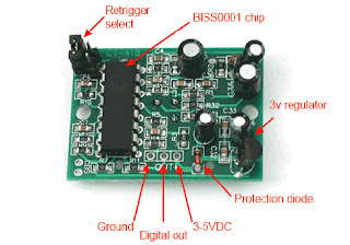
Most PIR modules have a 3-pin connection at the side or
bottom. The pinout may vary between modules so triple-check the pinout! It's
often silkscreened on right next to the connection. One pin will be ground,
another will be signal and the final one will be power. Power is usually 3-5VDC
input but may be as high as 12V. Sometimes larger modules don't have direct
output and instead just operate a relay in which case there is ground, power
and the two switch connections.
The output of some relays may be 'open collector' - that means it requires a
pullup resistor. If you're not getting a variable output be sure to try
attaching a 10K pullup between the signal and power pins.
An easy way of prototyping with PIR sensors is to connect it to a breadboard
since the connection port is 0.1" spacing. Some PIRs come with header on
them already, the ones from Adafruit don't as usually the header is useless to
plug into a breadboard.
By soldering
in 0.1" right angle header, a PIR is easily installed into a breadboard!
Step 3: Testing PIR


Once you have your PIR wired up its a good idea to do a
simple test to verify that it works the way you expect. This test is also good
for range testing. Simply connect 3-4 alkaline batteries (make sure you have
more than 3.5VDC out but less than 6V by checking with your multimeter!) and
connect ground to the - pin on your PIR. Power goes to the
+ pin. Then connect a basic red LED (red LEDs have lower forward voltages than
green or blue so they work better with only the 3.3v output) and a 220 ohm
resistor (any value from 100 ohm to 1.0K ohm will do fine) to the out pin
as shown. Of course, the LED and resistor can swap locations as long as the LED
is oriented connection and connects between out and ground
Now when the PIR detects motion, the output pin will go "high" to
3.3V and light up the LED!
Once you have the breadboard wired up, insert batteries and wait 30-60 seconds
for the PIR to 'stabilize'. During that time the LED may blink a little. Wait
until the LED is off and then move around in front of it, waving a hand etc,
to see the LED light up!
Retriggering

Once you have the LED blinking, look on the back of the PIR
sensor and make sure that the jumper is placed in the L position as shown
below. Now set up the testing board again. You may notice that when connecting
up the PIR sensor as above, the LED does not stay on when moving in front of it
but actually turns on and off every second or so. That is called
"non-retriggering". Now change the jumper so that it is in the H
position. If you set up the test, you will notice that now the LED does stay on
the entire time that something is moving. That is called
"retriggering"
For most applications, "retriggering" (jumper in H position) mode is
a little nicer. If you need to connect the sensor to something edge-triggered,
you'll want to set it to "non-retriggering" (jumper in L position)
Application area of PIR sensor:
- All
outdoor Lights
- Lift
Lobby
- Multi
Apartment Complexes
- Common
staircases
- For
Basement or Covered Parking Area
- Shopping
Malls
- For
garden lights
- All outdoor Lights
- Lift Lobby
- Multi Apartment Complexes
- Common staircases
- For Basement or Covered Parking Area
- Shopping Malls
- For garden lights


No comments:
Post a Comment