

Obstacle Avoiding Robot
The concept
of Mobile Robot is fast evolving and the number of mobile robots and their
complexities are increasing with different applications.There are many types of
mobile robot navigation techniques like path planning, self – localization and
map interpreting. An Obstacle Avoiding Robot is a type of autonomous mobile
robot that avoids collision with unexpected obstacles.
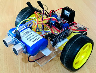
In this
project, an Obstacle Avoiding Robot is designed. It is an Arduino based robot
that uses Ultrasonic range finder sensors to avoid collisions.
Components Required
- Arduino Uno
- Ultrasonic Range Finder Sensor – HC – SR04
- Motor Driver IC – L293D
- Servo Motor (Tower Pro SG90)
- Geared Motors x 2
- Robot Chassis
- Power Supply
- Battery Connector
- Battery Holder
Circuit Diagram:

Components Description
Arduino

Arduino Uno
is an ATmega 328p Microcontroller based prototyping board. It is an open source
electronic prototyping platform that can be used with various sensors and
actuators.
HC-SRO4

It is an
Ultrasonic Range Finder Sensor. It is a non-contact based distance measurement
system and can measure distance of 2cm to 4m.
Servo Motor
The Tower
Pro SG90 is a simple Servo Motor which can rotate 90 degrees in each direction
(approximately 180 degrees in total).
Step 1: Chassis

The first
step and the base of any robot is a chassis. Either way, the chassis has to include a body, two motors
and sometimes even a battery holder and a switch.
The first
step and the base of any robot is a chassis. Either way, the chassis has to include a body, two motors
and sometimes even a battery holder and a switch.
Step2:Attaching Arduino
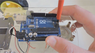
Now simply
use some screws to attach the Arduino to the chassis. If you've made your own
chassis/ can't find any screws, you can use a small amount of double-sided
tape. If you do choose to use double-sided tape then search for an area under
the Arduino that doesn't have many pins/solder above it.
Step3:Attaching Sensor
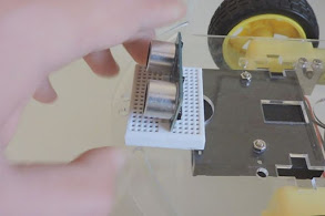
All we have
to do next is to actually attach the sensor to the body. To make life easier, it is recommend sticking a mini bread-board as well for easier wiring, although you
don't have to.
Step 4: Connecting Sensor to Arduino


Now gather
some wires, and connect the sensor to the Arduino according to this diagram is
made. Pay attention that your ping sensor may have a different pin layout (e.g.
5 pins), but it should have a voltage pin, ground pin, trig pin and an echo
pin.
Step 5: Connecting motor to Arduino

Arduino
boards can't control dc motors by their own, because the currents they are
generating are too low. Moreover, the currents they are generating cannot be
reversed, so you can't change the direction of the motor. To solve that we will
use a motor driver, which helps the Arduino control dc motors. The most
comfortable way of using motor drivers is through shields.
Finally
upload the Arduino Program and Obstacle avoiding robot is completely ready.


Thanks bro really helpful
ReplyDelete